
How to Choose the Right AWG Wire Gauge for XT60 and XT90 Connectors
Wire gauge and connector size must be selected together. A high-current connector attached to a thin lead is still limited by the wire, while an oversized wire can make a poor solder joint because it does not seat properly in the cup.
- Choose gauge from continuous current, not connector marketing current.
- XT60 is comfortable with 12–14 AWG.
- Keep battery leads short and use flexible silicone insulation.
Practical AWG guide
| Gauge | Typical short-lead current | Common use |
|---|---|---|
| 18 AWG | Around 15 A | Charging leads and small accessories |
| 16 AWG | Around 20 A | Compact battery packs |
| 14 AWG | Around 30 A | Standard XT60 battery leads |
| 12 AWG | Around 45 A | High-current XT60 and XT90 leads |
| 10 AWG | Around 60 A | XT90 and EC5 assemblies |
These figures assume short leads in open air. Bundled cables, high ambient temperatures and long runs all reduce the safe continuous current.
Connector fit and solder quality
XT60 accepts 12–14 AWG comfortably. XT90 generally suits 10–12 AWG. If the strands do not fit cleanly, do not cut half the conductor away to force the wire into the cup; choose the correct connector or use a professionally crimped transition.
Silicone versus PVC
Silicone stays flexible in cold conditions and tolerates soldering heat, making it the safer choice for RC packs, e-bikes and power tools. PVC is cheaper but stiffens at low temperature and can melt during poor hand soldering.
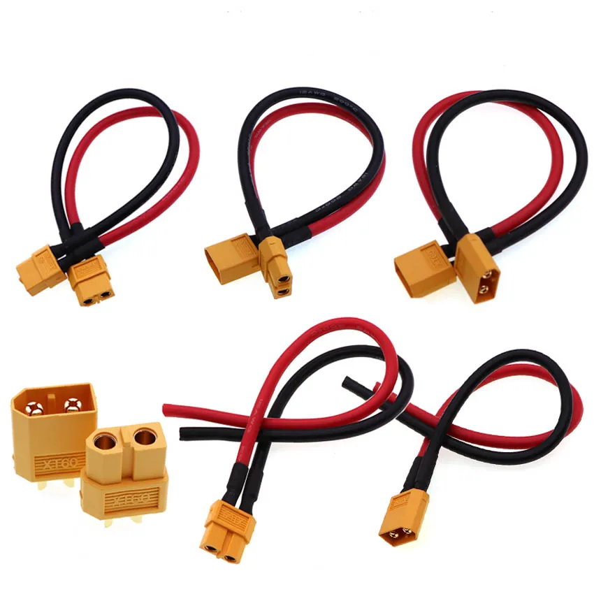
12AWG XT60 Male Female Conversion Plug Connection Cable With Silicone Extension Lead Wire Battery Connector To 10/20/50/100CM
12 AWG XT60 male/female conversion lead.
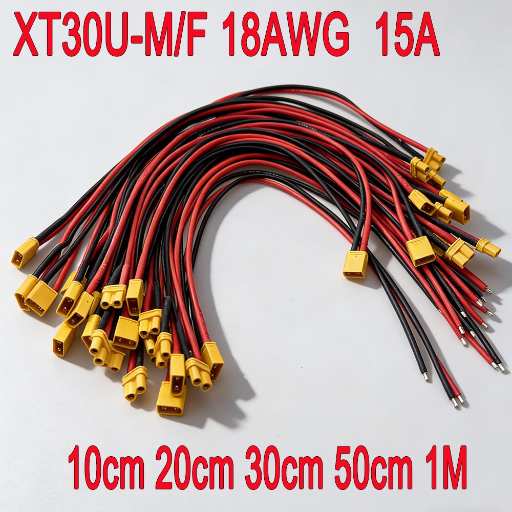
10CM-1M XT30 U-F/M Male to Female Plug Extension Cable Silicone Rubber Cable 18AWG Lithium Battery Plug With Wire Connector
Flexible XT30 extension cable in multiple lengths.
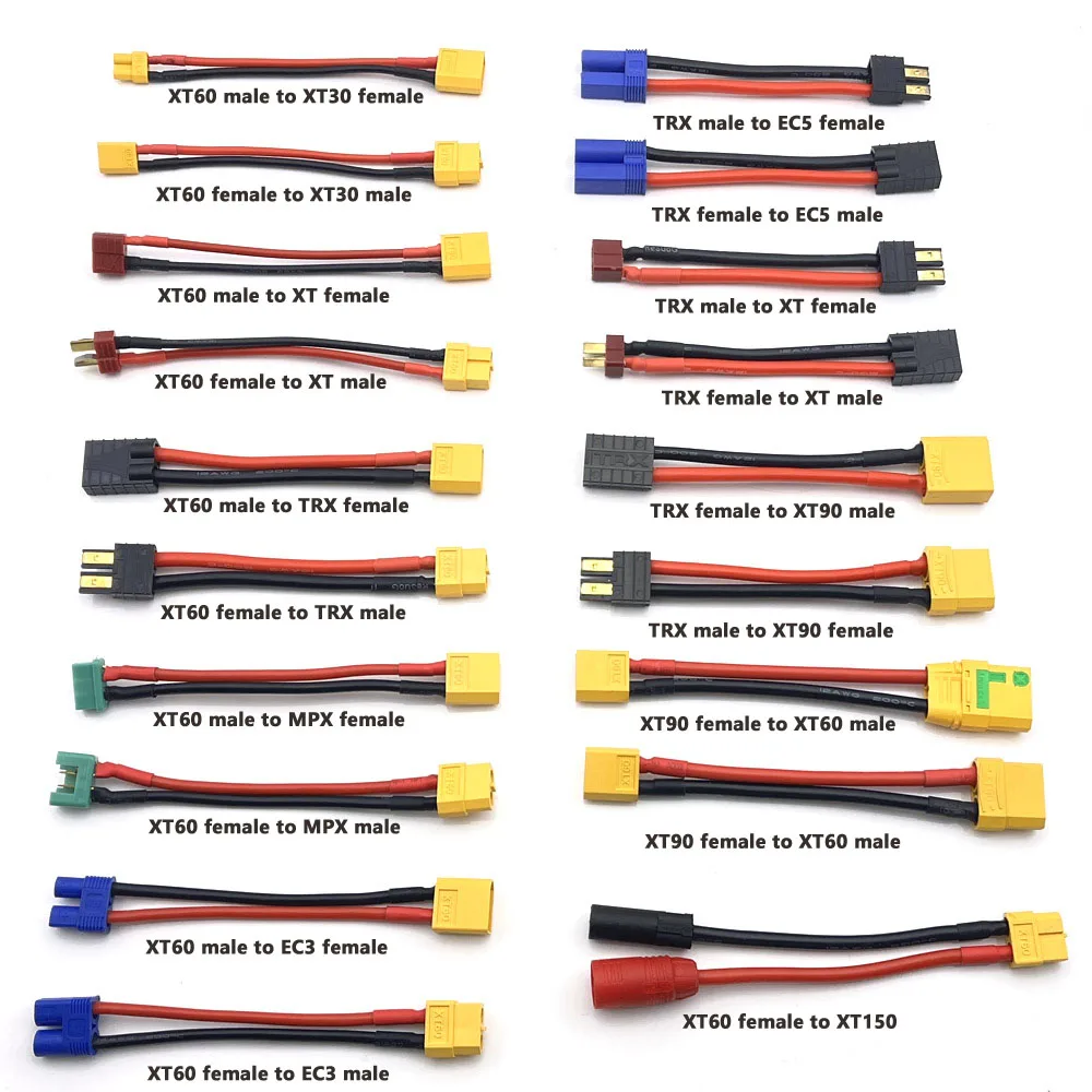
XT30 XT60 XT90 EC5 EC3 XT TPX MPX T Plug Female to Male Adapter Charge Connector 10cm Connector for RC Lipo Battery Parts DIY
XT30, XT60, XT90 and EC5 adapter combinations.
Three installation mistakes
- Selecting wire by connector size instead of current.
- Leaving exposed strands beside the solder cup.
- Skipping strain relief and heat-shrink at the joint.
Need a custom battery lead?
Send the connector type, wire gauge, length and target current. We can quote stock adapters or made-to-order assemblies.
Check voltage drop before buying the cable
Conductor resistance shows whether a short lead leaves enough voltage for the load. At 20°C, approximate copper conductor resistances are 20.95 mΩ/m for 18 AWG, 13.17 mΩ/m for 16 AWG, 8.29 mΩ/m for 14 AWG, 5.21 mΩ/m for 12 AWG and 3.28 mΩ/m for 10 AWG.
For a single conductor: Vdrop ≈ length × current × resistance per metre. A complete positive-and-negative run roughly doubles the drop. Example: two 0.5 m conductors of 12 AWG carrying 40 A have about 0.21 V conductor drop: (0.5 + 0.5) × 40 × 0.00521.
The loss rises with temperature, and connector contacts, fuses and terminals add further resistance. Measure the finished assembly instead of relying only on the calculation.
Acceptance checklist
- Current is the continuous operating value, not only an instantaneous peak.
- The connector solder cup or terminal accepts the full conductor without trimming strands.
- Insulation, heat-shrink and strain relief remain intact after flexing.
- Voltage drop and temperature rise are measured at the agreed load.
- Length tolerance and the measurement datum appear on the drawing.
Read the connector comparison next, or use the complete connector sourcing guide.