
XT60 vs XT90 vs EC5: Which Connector Should You Use?
XT60, XT90 and EC5 overlap enough that buyers often ask which one to standardise on. Start with continuous current and wire gauge; the connector follows from those two numbers.
- XT60: compact and typically used up to around 60 A.
- XT90: larger solder cups for 10–12 AWG and higher-current packs.
- EC5: spring-loaded bullets and a round housing for heavy-duty use.
Side-by-side comparison
| Connector | Typical current | Typical wire | Best fit |
|---|---|---|---|
| XT60 | Around 60 A | 12–14 AWG | 3S–6S LiPo packs, small e-bikes |
| XT90 | Around 90 A | 10–12 AWG | Larger scooters, high-current tools |
| EC5 | Around 120 A | 10–12 AWG | EV conversions and vibration-heavy packs |
How to choose
- Calculate continuous current, not the brief peak shown on a battery label.
- Confirm the selected connector accepts your wire gauge.
- Standardise one connector family within the project to eliminate adapters.
- Use anti-spark variants where high inrush current pits the contacts.
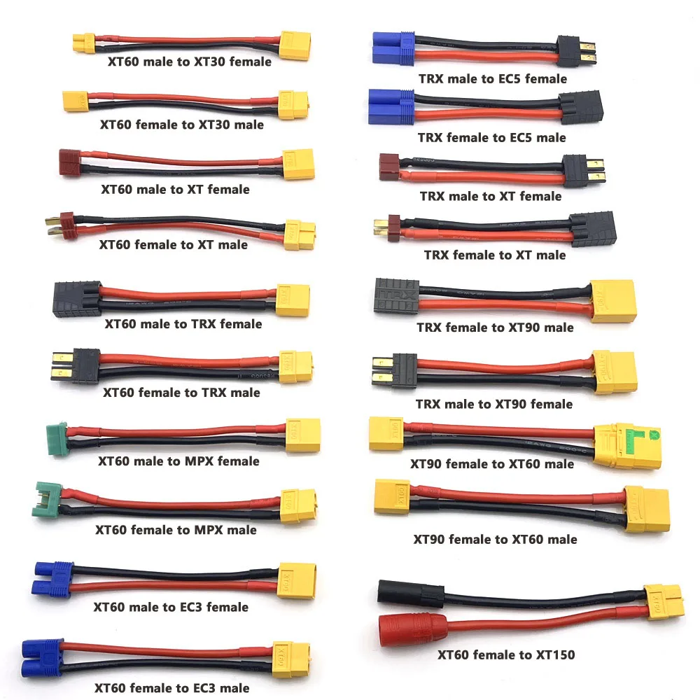
XT30 XT60 XT90 EC5 EC3 XT TPX MPX T Plug Female to Male Adapter Charge Connector 10cm Connector for RC Lipo Battery Parts DIY
Mixed XT30/XT60/XT90/EC5 adapter range.
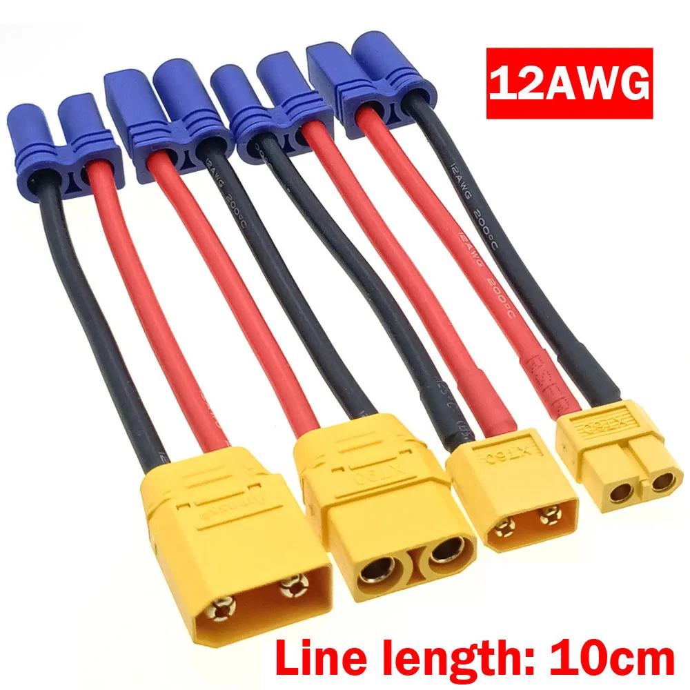
RC Car EC5 Connector Model Cars Charger Adapter Cable Battery Conversion Head EC5 Female Male To XT60 XT90 Male Female Head
EC5 to XT60/XT90 battery conversion cable.
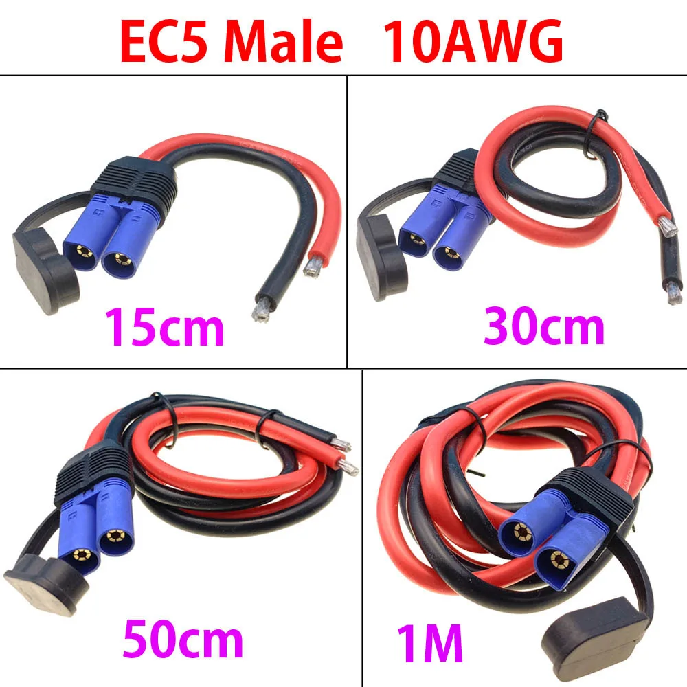
EC5 Male Female Plug10AWG Charging Cable For Car Motorcycle Emergency Power Cord EC5 Adapter Cord Conversion Accessories 15cm-1M
10 AWG EC5 charging and conversion lead.
Mating and safety
Keep the female receptacle on the battery side so exposed pins remain on the device side. Verify male/female orientation before soldering the pair, and never leave an adapter in a high-current line if a correctly terminated lead is available.
Building a high-current assembly?
Tell us the voltage, continuous current, wire gauge and required length. We will recommend XT60, XT90 or EC5 and quote the matched lead.
System-level selection matrix
| Application / load | Practical starting point | Verify before release |
|---|---|---|
| Small RC or 2S–4S pack below roughly 40 A continuous | XT30 or XT60 | Wire gauge, battery connector, duty cycle and temperature rise |
| 4S–6S pack around 40–60 A continuous | XT60 with 12–14 AWG | Joint quality, cable length and cooling |
| 6S–12S equipment around 60–90 A | XT90 with 10–12 AWG | Current sharing, connector authenticity and strain relief |
| High-vibration or higher-current EV / storage assembly | Evaluate EC5, AS150 or a project-specific connector | Full system validation; never use the nominal connector number as a test result |
These are selection starting points, not approval ratings. The battery, wire, connector, terminal, ambient temperature and duty cycle form one electrical system.
How to validate a candidate connector
- Test the complete mated assembly at the intended continuous current.
- Record voltage drop and surface temperature at thermal equilibrium.
- Repeat after temperature cycling and the expected vibration exposure.
- Define acceptance limits with the OEM specification, applicable standard or qualified supplier test report.
Continue with the AWG and voltage-drop calculation, or return to the connector selection and sourcing hub.
Need a higher-current battery connector?
For projects using larger battery packs or high-voltage storage assemblies, review the contact arrangement, keying, rated voltage and wiring together. Our 100–250 A, up to 1500 V DC connector is one reference option for this class of application.
View the 100–250 A high-voltage battery connector · Use the connector selection hub