
Pogo Pin and Magnetic Connectors: 2-Pin to 6-Pin Selection Guide for Buyers
Pogo-pin connectors look simple, but contact resistance, spring force and plating determine whether the connection remains stable after hundreds or thousands of mating cycles.
- Specify spring force in grams-force, not only pin count.
- Gold thickness is a major driver of mating life and price.
- Add a redundant power pin on frequently connected charging interfaces.
Five numbers to put in the RFQ
| Parameter | Typical range | Why it matters |
|---|---|---|
| Spring force | 30–150 gf per pin | Too light causes intermittent contact; too heavy wears the socket |
| Contact resistance | 20–50 mΩ initial | Controls heating and voltage drop |
| Current per pin | 1–5 A | Sets the minimum number of power pins |
| Plating | Gold flash to several µin | Sets corrosion resistance and cycle life |
| Mating cycles | 5,000–100,000 | Charging docks need a much higher target |
From 2-pin to 6-pin
Calculate the current first, then add signal, ID or temperature pins. More pins increase cost and mating force. Decide the pitch early: 2.54 mm is widely available, while smaller pitches often trigger new tooling.
When magnetic retention pays
Magnets add cost, but they allow one-handed docking and remove a mechanical latch that could break in the field. They are most valuable on wearables, charging docks, portable equipment and exposed charging ports.
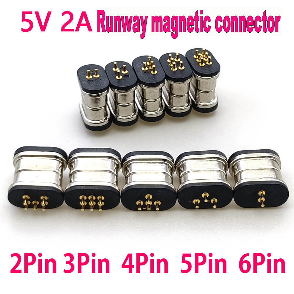
DC Magnetic Pogo Pin Connector 5V 2A 2Pin 3Pin 4Pin 5Pin 6Pin Spacing 2.54mm Pogopin Male Female Spring Loaded DC Power Socket
2–6 pin magnetic pogo-pin connector family.
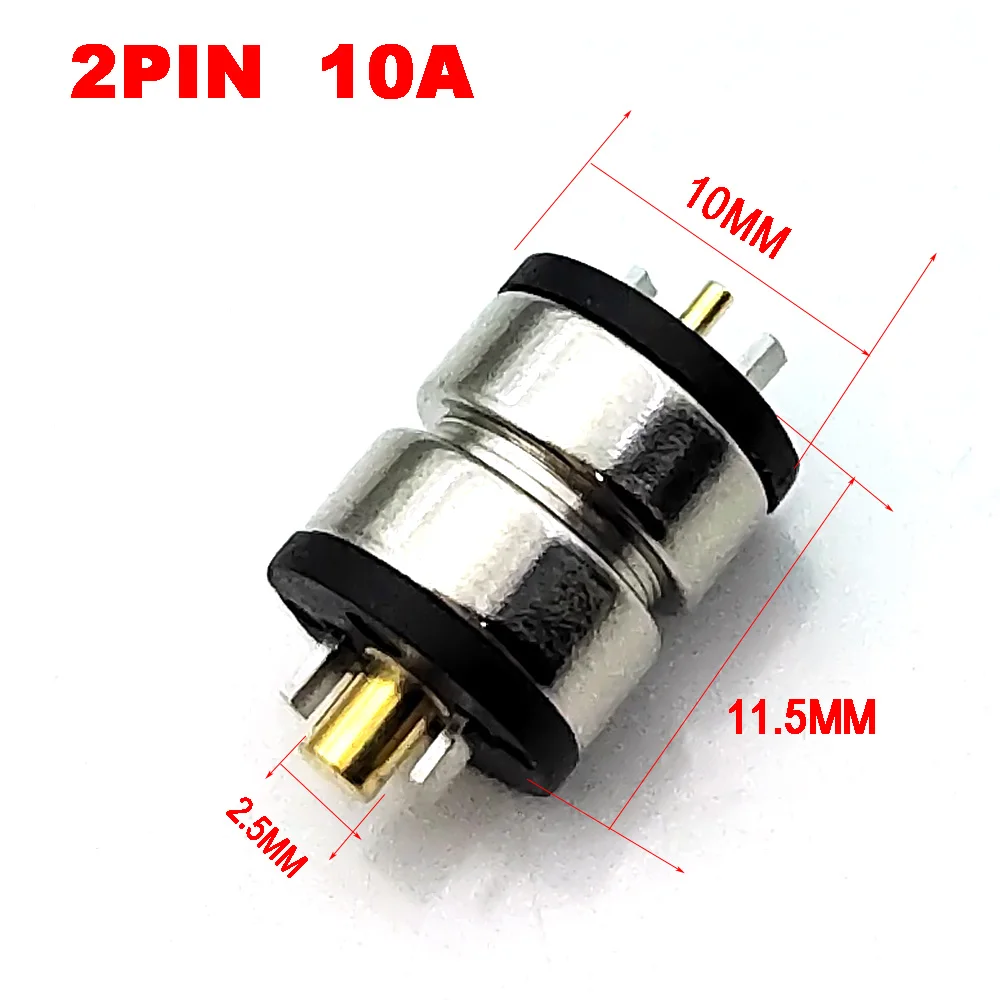
10mm Round 10A High Current Magnet Suction Spring Pogo Pin Connector Male Female Probe DC Power Charging Magnetic Connector
10 mm round 10 A high-current magnetic connector.
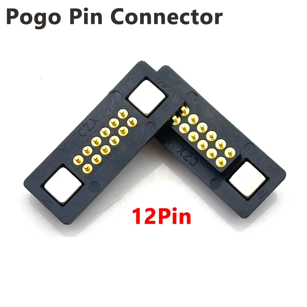
2pin 3pin 4pin 5pin 6pin 7pin 8pin 9pin 10pin 11pin 12Pin 2A High Current Magnet Suction Spring Pogo Pin Male Female Probe DC Power Magnetic Connector
High-pin-count spring-loaded magnetic connector.
Custom-project checklist
- Sample lead time and first-article approval.
- Tooling cost and ownership.
- Batch spring-force and contact-resistance report.
- Protected packing for pin tips.
Need a sample pack?
Share the pin count, pitch, current per pin, cycle target and drawing. We will quote a stock or custom pogo-pin solution.
Pin-count planning matrix
| Interface requirement | Starting configuration | Additional checks |
|---|---|---|
| Low-current power only | 2 power pins | Current per pin, polarity, spring force and reverse protection |
| Power plus temperature or identification | 3–4 pins | Signal isolation and assignment on both mating faces |
| Multiple voltage rails or data lines | 5–6 or more pins | Pitch, keying, contact resistance and route planning |
| High-current docking interface | Parallel power pins or larger contacts | Current sharing, temperature rise and pin-wear inspection |
Mechanical and electrical validation
- Confirm axial retention and resistance to side-loading in the installed orientation.
- Verify magnet polarity and mechanical keying prevent reverse mating.
- Measure contact resistance after the planned number of mating cycles.
- Test at the intended load because spring force changes over the product life.
- Inspect plating, solderability, burrs and protected packing.
Compare the wire and termination requirements, or return to the connector buying-guide hub.