
Why Connectors Fail: Soldering, Current Rating and an Incoming Inspection Checklist
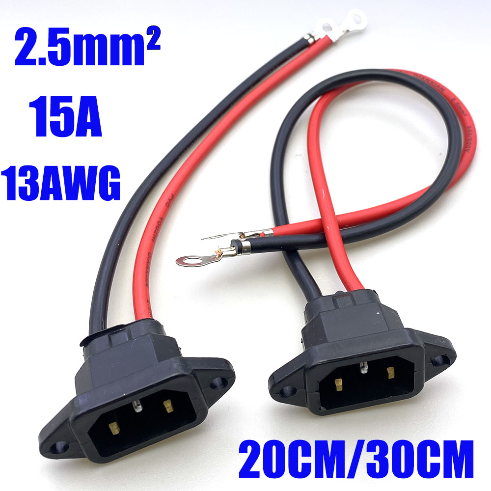
Connector failures usually trace back to four measurable conditions: excessive contact resistance, poor soldering or crimping, vibration fatigue and contamination or mismatched plating.
- Heat rises with resistance × current squared.
- A high-current connector cannot compensate for undersized wire.
- Most field failures begin at the wire-to-terminal transition.
Heat and resistance
A 20 mΩ contact looks harmless until it carries 30 A. The resulting heat accelerates oxidation and raises resistance further. Test a mated sample with a milliohm meter and run the assembly at rated current long enough to measure temperature rise.
Cold or contaminated joints
- Require pre-tinning and a controlled soldering window.
- Inspect solder wicking and limit exposed strands.
- For crimped terminals, pull-test the crimp and verify the insulation grip.
Vibration and moisture
Strain relief within 30 mm of the connector, adhesive-lined heat-shrink and correct cable support prevent most fatigue failures. Spring-loaded contacts are useful where vibration is severe.
Inspection checklist
| Check | Method | Typical target |
|---|---|---|
| Contact resistance | Milliohm meter on mated pair | ≤50 mΩ initial |
| Continuity / short | 100% harness test | Correct pin map, no shorts |
| Crimp pull force | Tensile test | Per terminal specification |
| Temperature rise | 30 min at rated current | ≤30 K above ambient |
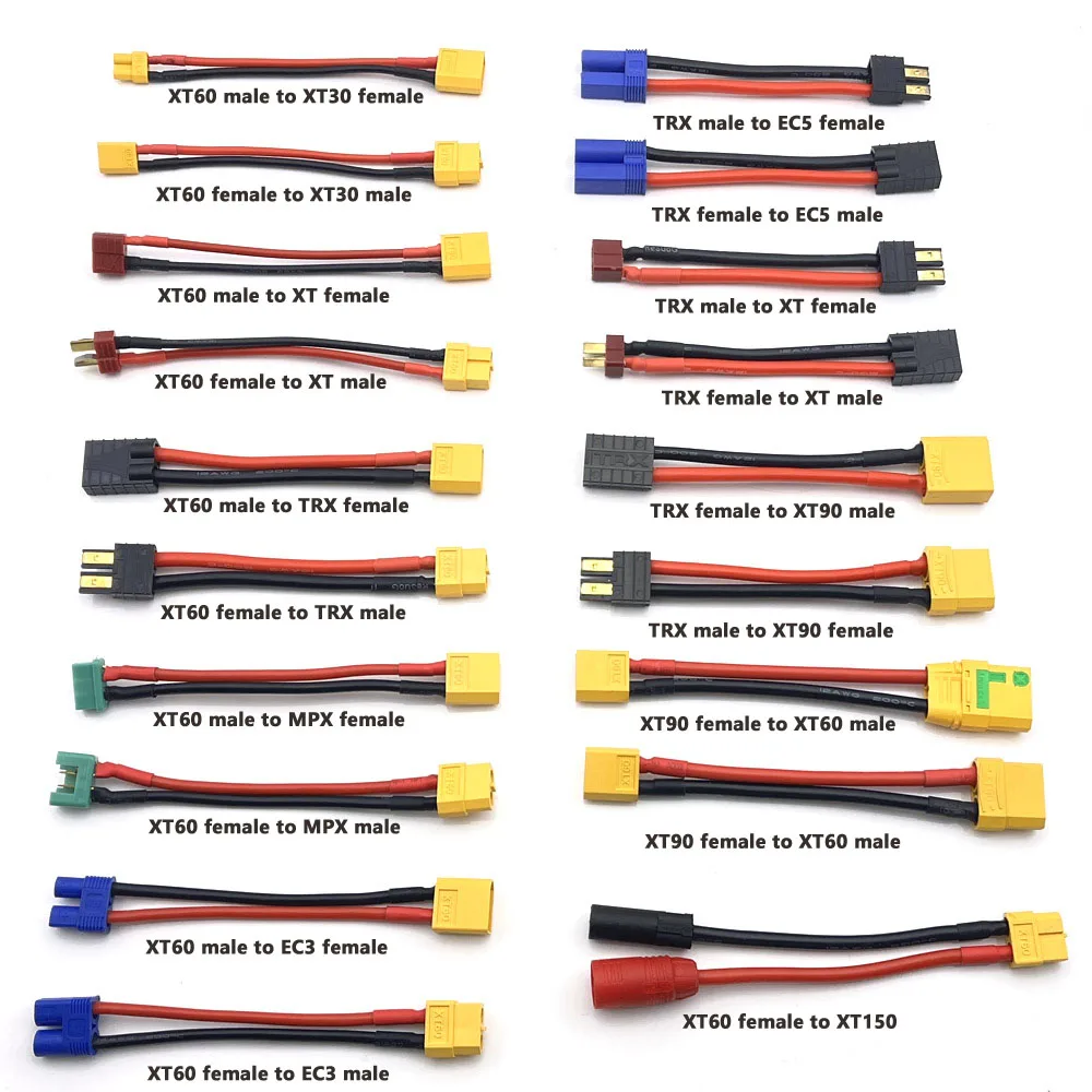
XT30 XT60 XT90 EC5 EC3 XT TPX MPX T Plug Female to Male Adapter Charge Connector 10cm Connector for RC Lipo Battery Parts DIY
Mixed power-connector adapters for test and production builds.
Waterproof 15A 250V IEC320 C13 C14 Corded Plug Connector for Electric Bikes and Cars Battery Charging AC Power Outlet
Waterproof corded AC power connector.
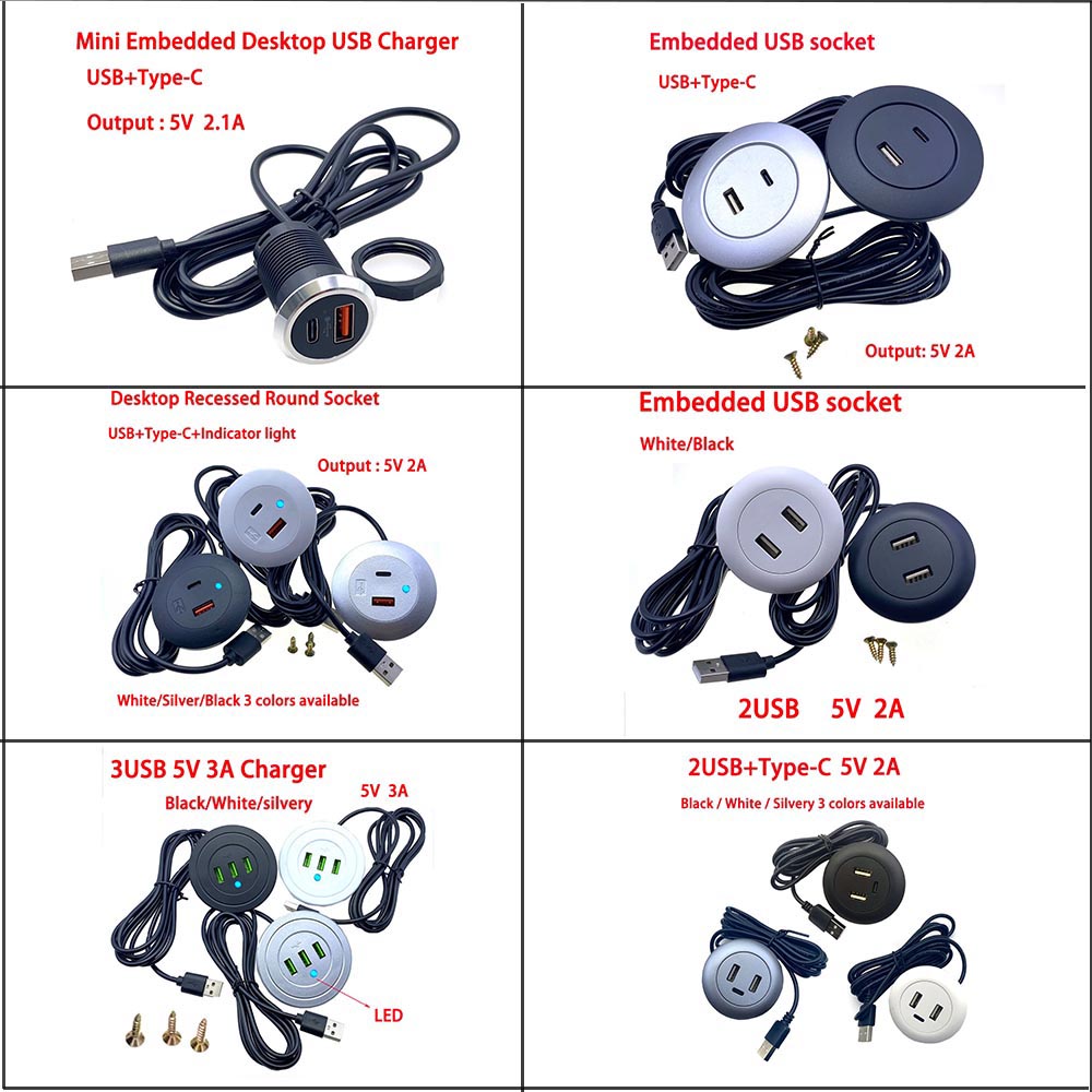
USB+Type-C Multi Port Desktop Embedded Charging Connector 5V 2A/3A For Mobile Phone USB Desk Data Line Splitter Charging Socket
USB / Type-C desktop charging connector.
Need QC requirements in the quote?
Tell us the tests and acceptance limits you need. We can include an inspection plan and batch report with the quotation.